Last week we looked at the physical specifications of
the Arista Networks 7050SX-64 Ethernet Switch, and today we'll discuss redundancy in Arista equipment using the MLAG configuration.
MLAG (Multi-Chassis Link Aggregation Group) Configuration.
Arista does not offer equipment with stacking ports in its product portfolio. So how is it able to provide both physical and logical redundancy in its networks? Arista uses the MLAG concept to address this type of scenario.
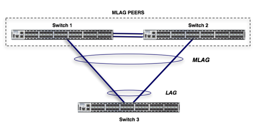
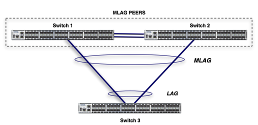
Let’s look at an example. Imagine the following scenario, in which we want to provide Switch 3 with both physical and logical redundancy for its upper layer. To do this, we’ll configure MLAG so that Switch 3 sees Switches 1 and 2 as a single logical entity.
 NOTE:
NOTE: It is recommended that both ends of the MLAG use the same EOS image. Using different EOS images may cause adjacency issues.
Step 1. – Create the port channel for the peer link
The peer link is responsible for establishing and maintaining the MLAG association between sw1 and sw2.
We assume that the eth1 and eth2 interfaces on both switches (sw1 and sw2) are the ones that will be connected via the peer link, and we perform the following configuration.
Using a port channel to establish the peer link is not mandatory, but it is a recommended best practice.
switch1# config t
switch1(conf)#interface eth1-2
switch1(config-if-Et1-2)# channel-group 10 mode active
switch1(config-if-Et1-2)# interface port-channel 10
switch1(config-if-Po10)# switchport mode trunk
switch2# config t
switch2(conf)#interface eth1-2
switch2(config-if-Et1-2)# channel-group 10 mode active
switch2(config-if-Et1-2)# interface port-channel 10
switch2(config-if-Po10)# switchport mode trunk
Step 2. Create a VLAN for MLAG peer-to-peer communication
switch1(conf)#vlan 4094
switch1(config-vlan-4094)# trunk group mlagpeer
switch1(config-vlan-4094)# interface port-channel 10
switch1(config-if-Po10)# switchport trunk group mlagpeer
switch1(config-if-Po10)# exit
switch1(conf)#no spanning-tree vlan 4094
switch2(conf)#vlan 4094
switch2(config-vlan-4094)# trunk group mlagpeer
switch2(config-vlan-4094)# interface port-channel 10
switch2(config-if-Po10)# switchport trunk group mlagpeer
switch2(config-if-Po10)# exit
switch2(conf)#no spanning-tree vlan 4094
NOTE: The trunk group name and the VLAN must be identical at both ends. Additionally, assigning VLAN 4094 and Po10 to the same trunk group ensures that the VLAN will only be carried on that trunk. Once this is done, it is safe to disable Spanning Tree to ensure communication between the MLAG peers.
Step 3. Configure Level 3 for peer-to-peer communication
switch1(conf)#int vlan 4094
switch1(config-if-Vl4094)# ip address 10.10.0.1/30
switch2(conf)#int vlan 4094
switch2(config-if-Vl4094)# ip address 10.10.0.2/30
Step 4. Configure the MLAG peer on both switches
switch1(config)#mlag
switch1(config-mlag)#local-interface vlan 4094
switch1(config-mlag)#peer-address 10.10.0.2
switch1(config-mlag)#peer-link port-channel 10
switch1(config-mlag)#domain-id mlag10
switch2(config)#mlag
switch2(config-mlag)#local-interface vlan 4094
switch2(config-mlag)#peer-address 10.10.0.1
switch2(config-mlag)#peer-link port-channel 10
switch2(config-mlag)#domain-id mlag10
For the MLAG adjacency relationship to be established, the following conditions must be met:
- Peer-link up
- The domain IDs must match
- Establish bidirectional TCP communication
Step 5. Check MLAG
Show mlag and verify that the status is active
switch1#show mlag
MLAG Configuration:
domain-id : mlag10
local-interface : Vlan4094
peer-address : 10.10.0.2
peer-link : Port-Channel10
MLAG Status:
state : Active
peer-link status : Up
local-int status : Up
system-id : 00:33:22:01:03:01
switch2#show mlag
MLAG Configuration:
domain-id : mlag10
local-interface : Vlan4094
peer-address : 10.10.0.1
peer-link : Port-Channel10
MLAG Status:
peer-link status: Up
local-int status: Up
system-id: 00:33:22:01:03:01
Step 6. Configure MLAG between SW1-SW2 and SW3
The final configuration step is to create a port channel between sw1 and sw3 and between sw2 and sw3, ensuring they share the same MLAG ID
switch1(conf)#interface eth3
switch1(config-if-Et3)# channel-group 3 mode active
switch1(config-if-Et3)# interface port-channel 3
switch1(config-if-Po3)# mlag 3
switch2(conf)#interface eth3
switch2(config-if-Et3)# channel-group 3 mode active
switch2(config-if-Et3)# interface port-channel 3
switch2(config-if-Po3)# mlag 3
On sw3, the configuration could be set up using an LACP link in a port-channel
NOTE: For the MLAG identifier, keep the following in mind
- The MLAG ID does not have to match the port-channel ID
- For port-channels grouped in an MLAG, the IDs must match
- A port-channel in an MLAG can have multiple members
Step 7. Verify the MLAG port channels
The last step is to verify the port-channel status. In the output of the following command, we can see that MLAG 3 has been active for 3 minutes
switch1#sh mlag | grep Active
state : Active
Active-partial : 0
Active-full : 2
switch1#sh mlag interfaces detail
local/remote
| mlag |
state |
local |
remote |
oper |
config |
last change |
changes |
| 3 |
active-full |
Po3 |
Po3 |
up/up |
ena/ena |
0:02:17 |
Aug. 6 |
With the steps above, we'll wrap up this new blog post, in which we've configured an MLAG between two Arista switches on one end and a switch from any other vendor with LACP functionality on the other end. See you in future posts.