In the previous blog post
"Juniper EX3300 Ethernet Switch" We looked at the main physical and software features of the EX3300 switches. Among the key physical and software features, one stood out above all others: the ability to configure up to 10 switches as if they were a single chassis. This feature, called Virtual Chassis, is what we’ll be discussing in this post.
Juniper EX3300 switches come with 2 of the 4 uplink ports preconfigured by default to connect and form the Virtual Chassis. These two Virtual Chassis ports (VCPs) are ports 2 and 3—that is, the ports farthest to the right when facing the switch head-on.
What cables do we need to connect the devices to each other?
Well, this is one of the advantages of Juniper Networks’ EX3300 switches: no specific stacking cables are required to connect the devices. To connect Juniper EX3300 devices and form the Virtual Chassis, you need a transceiver compatible with the devices and a fiber or copper cable, which makes deployment easier.
To download the list of all transceivers compatible with the Juniper EX3300 Ethernet Switch, click
here.
How are the devices connected to form the Virtual Chassis?
To set up the Virtual Chassis, the Juniper EX3300 switches must be connected to form a ring. The best way to understand this is to look at some examples
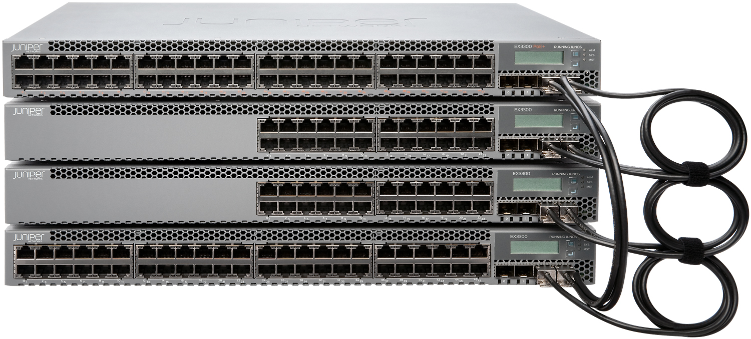
Example 1. EX3300 switches mounted in a rack and connected in a ring topology
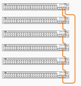
Example 2. EX3300 switches mounted in a rack and connected in a ring topology
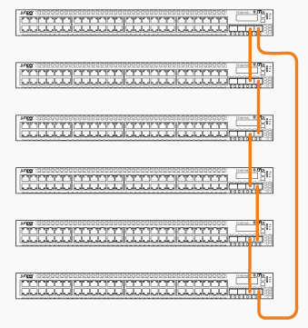
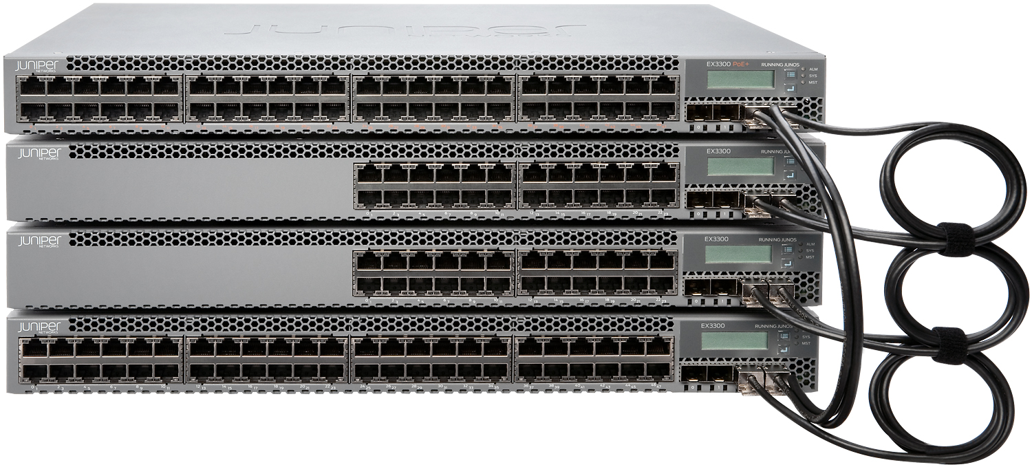
Example 3. EX3300 switches mounted in a rack and connected in a ring topology
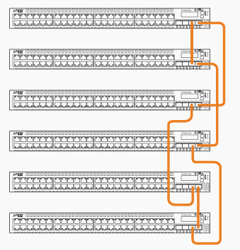
Configuring the Juniper EX3300 Ethernet Switch as a Virtual Chassis
Once the Juniper EX3300 switches are physically connected, you must configure the devices. For a Virtual Chassis to function properly, you must define a role for each member.
These roles can be:
- Master (routine-engine)
- Backup (routine-engine)
- Other (line-card)
When a switch is defined as having the routine-engine role, it can be selected as either the master or backup of the Virtual Chassis; if the role is line-card, it cannot be selected as master or backup.
If you do not want to predefine the roles, the EX3300 switches will manage themselves and select roles automatically.
In this case, we will look at the two ways to configure Juniper EX3300 switches.
Option 1. Configuring the Juniper EX3300 as a Virtual Chassis with the default roles.
To configure the system using the preset roles, follow these steps:
1. Make a list of the serial numbers of the devices that will be part of the Virtual Chassis
2. Define the roles of each device (routine-engine or line-card)
3. Interconnect the devices using the uplink ports
4. Power on the device you want to be the master. The other devices must remain powered off
5. Launch EZSetup on the master switch
6. Configure the VME (Virtual Management Ethernet) interface for out-of-band configuration of the Virtual Chassis
user@switch# set interfaces vme unit 0 family inet address /ip-address/mask/
7. Specify the pre-provisioned mode in configuration mode
[edit virtual-chassis]
user@switch# set preprovisioned
8. Specify the members that will be part of the Virtual Chassis. List each switch with its serial number and the desired member ID
user@switch# set member 0 serial-number abc123 role routing-engine
user@switch# set member 1 serial-number def456 role line-card
user@switch# set member 2 serial-number ghi789 role line-card
user@switch# set member 3 serial-number jkl012 role line-card
user@switch# set member 4 serial-number mno345 role line-card
user@switch# set member 5 serial-number pqr678 role routing-engine
9. (Optional). When the virtual chassis consists of only two members, you must disable “Split and Merge”
user@switch# set no-split-detection
10. Boot the remaining switches
Option 2. Configuring the Juniper EX3300 as a Virtual Chassis without predefined roles.
To configure the system using the predefined roles, follow these steps:
1. Interconnect the devices using the uplink ports.
2. Power on the device you want to be the master. The other devices must remain powered off.
3. Start EZSetup on the master switch
4. Configure the VME (Virtual Management Ethernet) interface for out-of-band configuration of the Virtual Chassis
user@switch# set interfaces vme unit 0 family inet address /ip-address/mask/
5. Configure the mastership priority for the master, backup, and other members
[edit virtual-chassis]
user@SWA–0# set member 0 mastership-priority 255
user@SWA–0# set member 3 mastership-priority 255
6. (Optional). When the Virtual Chassis consists of only two members, you must disable Split and Merge
user@switch# set no-split-detection
10. Power on the remaining switches sequentially, depending on whether you want them to serve as backups or other roles.